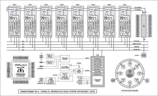
Parallel Port Band Code Translator


This project has been rendered unnecessary by changes in WriteLog. It is being kept on the site as an example of a very simple Parallax Propeller application.
The problem is a simple one. WriteLog used one set of binary codes for the LPT band switch output for 50 MHz through 24 GHz, and my station, based on the PackRats' N3FTI Logging Band Interface, used another set of binary codes. And I REALLY wanted to use WriteLog, and didn't want to have to rewire my bandswitch. So I quickly wrote up the plans for this simple decoder or translator, which is simply inserted inline with the LPT cable that runs between the WriteLog computer and my bandswitch. However, Wayne K5XD is so very responsive to users' input, that before the parts for this device were even shipped to me, he had modified WriteLog to take care of this problem. Nevertheless, I leave this here as a very simple example of what can be done with a Parallax Propeller chip.
The propeller takes input from the LPT port of the computer and recodes it to what the N3FTI board needs and sends the required output to the N3FTI board. The program is written so that if the input band code changes, it is a simple matter to reassign the 0-15 input codes to the output band codes F50 through F24G. A 74LS75 Latch is used to keep band switching from occurring while the station is transmitting. The 74LS75 Latch can be placed on either the input or output side of the Propeller. PS2505 Optoisolators on protect the Propeller chip. A preliminary schematic is here.
The code is listed below, and also in this hyperlink. The first two-thirds or so are just documentation:
{{ LPTCode.spin
| Band | A | B | C | D |
| 160 | 1 | 0 | 0 | 0 |
| 80 | 0 | 1 | 0 | 0 |
| 40 | 1 | 1 | 0 | 0 |
| 30 | 0 | 0 | 1 | 0 |
| 20 | 1 | 0 | 1 | 0 |
| 17 | 0 | 1 | 1 | 0 |
| 15 | 1 | 1 | 1 | 0 |
| 12 | 0 | 0 | 0 | 1 |
| 10 | 1 | 0 | 0 | 1 |
| 50 | 0 | 1 | 0 | 1 |
| 144 | 1 | 1 | 0 | 1 |
| 222 | 0 | 0 | 1 | 1 |
| 432 | 1 | 0 | 1 | 1 |
| 903 | 0 | 1 | 1 | 1 |
| 1296 | 1 | 1 | 1 | 1 |
| 2304 | 1 | 0 | 0 | 0 |
| 3456 | 0 | 1 | 0 | 0 |
| 5760 | 1 | 1 | 0 | 0 |
| 10G | 0 | 0 | 1 | 0 |
| 24G | 1 | 0 | 1 | 0 |
| 47G | 0 | 1 | 1 | 0 |
| 75G | 1 | 1 | 1 | 0 |
| 119G | 0 | 0 | 0 | 1 |
A = LPT pin 2 Least Significant
B = LPT pin 7
C = LPT pin 8
D = LPT pin 9 Most Significant
Gnd = LPT pin 15
The output signal matrix is as follows:
| Band | A | B | C | D |
| 50 | 0 | 0 | 0 | 0 |
| 144 | 1 | 0 | 0 | 0 |
| 222 | 0 | 1 | 0 | 0 |
| 432 | 1 | 1 | 0 | 0 |
| 903 | 0 | 0 | 1 | 0 |
| 1296 | 1 | 0 | 1 | 0 |
| 2304 | 0 | 1 | 1 | 0 |
| 3456 | 1 | 1 | 1 | 0 |
| 5760 | 0 | 0 | 0 | 1 |
| 10G | 1 | 0 | 0 | 1 |
| 24G | 0 | 1 | 0 | 1 |
| Others | 0 | 0 | 0 | 0 |
A = LPT pin 2 Least Significant
B = LPT pin 7
C = LPT pin 8
D = LPT pin 9 Most Significant
Gnd = LPT pin 15
LPT Pin 2 connects to Pin 0
LPT Pin 7 connects to Pin 1
LPT Pin 8 connects to Pin 2
LPT Pin 9 connects to Pin 3
Pin 11 connects to LPT Pin 2 out
Pin 12 connects to LPT Pin 7 out
Pin 13 connects to LPT Pin 8 out
Pin 14 connects to LPT Pin 9 out
END OF DOCUMENTATION; code follows:
}}
VAR
long temp[4]
long freq
long stack[9]
PUB Main
cognew(toggle(3_000_000),
@stack)
convlpt
PUB toggle(Delay)
dira[16]~~
repeat
!outa[16]
waitcnt(Delay + cnt)
PUB convlpt
dira[11..15]~~
dira[0-3]~
repeat
temp:=INA[3..0]
freq := temp[0] + (2*temp[1]) + (4*temp[2]) + (8*temp[3])
case freq
'0
1: F2304
2: F3456
3: F5760
4: F10G
5: F24G
' 6: F47G
' 7: F75G
' 8: F119G
' 9: F142G
10: F50
11: F144
12: F222
13: F432
14: F903
15: F1296
OTHER: F50
PUB F50
outA[11..14]:= %0000
PUB F144
outA[11..14]:= %0001
PUB F222
outA[11..14]:= %0010
PUB F432
outA[11..14]:= %0011
PUB F903
outA[11..14]:= %0100
PUB F1296
outA[11..14]:= %0101
PUB F2304
outA[11..14]:= %0110
PUB F3456
outA[11..14]:= %0111
PUB F5760
outA[11..14]:= %1000
PUB F10G
outA[11..14]:= %1001
PUB F24G
outA[11..14]:= %1010
The code is compiled using the free
Propeller Tool software
by Parallax.
Copyright 1997-2007 COPYRIGHT Roger Rehr W3SZ. All Rights Reserved