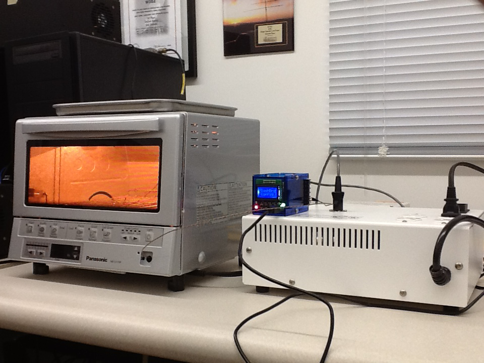
Homebrew Reflow Oven
by
Roger Rehr, W3SZ

I. Introduction. Hand soldering of smaller multi-leaded SMA components can be extremely challenging. Hand soldering of ball grid array (BGA) devices is even more problematic. And complex projects involving dozens of SMA components, even though they can be done by hand soldering, can be extremely tedious.
For these reasons, as my projects have become more complex and have involved ever smaller components with more and more leads per component, I have wanted a better solution than hand soldering. After looking at possible alternatives to hand soldering such as hot air guns1 and hot plates2, I decided that a reflow oven3 would be the best choice for these projects with one or more of the following characteristics: very small SMA components, BGA devices, a high device count.
I looked at commercially available reflow ovens, and found that they were priced starting at $3004, with most of the units that looked reasonable in terms of quality, reliability, and features being priced at $6005 and up. I completed this project in 2013. At that time there had been one KickStarter reflow oven project, called RefloLeo6. Since then there have been several more, including Zallus7, Reflowster8, ControLeo29, and several others10, some of which were canceled11.
In addition, there were then and now are an even greater number of webpages describing homebrew reflow ovens, all based on simple toaster ovens12 13 14 15. I have given references for four such webpages, but there were dozens available. Most of these projects had in common three key features:
1. They looked very easy to construct
2. They looked like they would be much cheaper than the commercial alternatives
3. The builders were uniformly happy with the performance of their creations
In addition, I noted that there were a number of discouraging reports on the less expensive commercial ovens (e.g the T962A), with reported problems including uneven heat distribution, burning of PCBs, etc16 17. Although some solutions to these problems were offered, it seemed to me to make more sense to look for a system that did not have sub-optimal results requiring correction in the first place.
I was not enthusiastic about the KickStarter projects because each of them was in some way limited, and I felt that I could myself assemble a more versatile, more extendable controller / reflow oven.
So I decided to make my own reflow oven, using a PID18 (Proportional-Integral-Derivative) controller to control the temperature. After reviewing the various projects found on the web I decided to use the osPID19 as my PID controller because it was very flexible, easy to use, and had a nice software package backing it up20, and because a user reported good results using it for a reflow oven controller21. Furthermore, because the osPID is open source, I had confidence that I could write new software for it if necessary (it turned out that was not necessary).
The name of the osPID is derived from “os” for open source and PID for Proportional-Integral-Derivative. The osPID is a collaboration between Rocket Scream Electronics, creators of the Arduino Reflow Controller Shield22, and Brett Beauregard, creator of the Arduino PID Library23. It consists of an Arduino compatible board, an 8 x 2 alphanumeric character LCD display, a 4 push button navigation interface, a USB converter chip for communication with a PC, and input and output cards including a type K thermocouple input port, all enclosed in a PID form factor case24.
Other than odds and ends, the components for this project consisted of:
1. Toaster Oven
2. osPID controller
3. Solid State Relay
4. Type K thermocouple
I decided to use a Panasonic NB-G110P Flash Xpress Toaster Oven, which I obtained from Amazon for $101.99. Many of you will have an old toaster oven. If you use that, you will reduce the cost of this project by 50%. I chose this oven because it was used with good results by someone who had built a reflow oven using the osPID as a controller, so I knew that it would do the job.
I obtained the osPID from RocketScream for $85.0025.
I got my Solid State Relay (SSR) from Amazon. It was an Amico SSR-40 DA Single Phase Solid State Relay SSR 40A 3-32V DC 24-380V AC w Heat Sink and it cost $11.45. I could have gotten one from eBay for less than $5 without a heatsink26.
The Type K thermocouple was a model SEN-00251 Thermocouple Type-K Glass Braid Insulated from SparkFun, which cost $13.9527.
So my cost of major components, including toaster oven, was $212.39. For this price I got a unit that I believe is better than commercial units costing several times my expenditure, and I have the pride of using a homebrew creation rather than a commercially produced appliance when I reflow solder my homebrew PCB projects.
If you have your own toaster oven, then your costs would be limited to the OSPID, the SSR, and the thermocouple, the cost of which totals $110.40.
From my junkbox I got the cabinet into which I installed the SSR and the connectors I used to connect the OSPID and the toaster oven to the SSR.
II. Theory. Reflow Soldering. Reflow soldering is the process in which solder paste is used to temporarily attach electrical components to contact pads on a circuit board, after which the entire assembly is subjected to controlled heat which melts the solder and permanently connects the component to the board physically, and with an excellent low-resistance electrical connection as well.
There are four consecutive stages to reflow soldering. These phases are generally called preheating (or ramp-to-soak), soak, reflow, and cooling. The picture below shows a reflow profile for Kester Easy Profile 256 No-Clean Solderpaste (EP256), which is what I use.
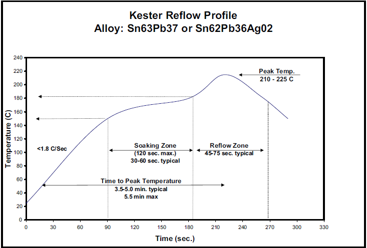
As you
can see in the image on the left, for Kester EP 256 the preheat
stage lasts 90 seconds, and takes the temperature from 20 C up to 150 C.
During this stage the solvent in the solder paste begins to
evaporate. If the rate of temperature rise is too low, evaporation
of the volatile components of the flux is incomplete. If the rate of rise is too fast, it can lead to
component damage, cracking, and spattering of solder paste.
For EP256, the soak stage runs from 90 seconds through ~190 seconds. During this stage
evaporation of the volatile components of the flux is completed and
the flux is activated, initiating oxide reduction on component leads
and PCB pads. If the temperature during this phase is too high
oxidation of the paste, pads and component leads can occur, as well
as solder spattering and balling. If the temperature is too low,
then the flux may not activate fully.
For this solder the reflow stage extends from ~190 through ~265 seconds. During this stage the solder
becomes liquid (melts) and surface tension is reduced, allowing metallurgical bonding and giving a good solder joint. Maximal
acceptable peak temperature is determined by the component with the lowest tolerance
for high temperatures. Excessive peak temperature, in addition to
damaging components, may foster intermetallic growth and brittle solder joints, and cause PC board damage.
Insufficient peak temperature may prevent adequate reflow. If the
time of this stage is too long, then flux may be prematurely
activated or consumed, leading to a dry solder joint. Excessive
length of this stage may also cause intermetallic growth and brittle
solder joints, just as does excessive peak temperature. If the duration/temperature for
this stage
are insufficient, then inadequate removal of solvent and flux, as
well as inadequate reflow may
result, leading to cold, dull, defective
solder joints
as well as solder voids.
The
cooling
stage for EP256 begins at ~265 seconds. During this stage the board and
components are gradually cooled to ambient temperature. A cooling
rate of 4C/sec is often suggested. Proper cooling rates minimize the
chances of thermal shock and intermetallic formation.
Oven
and Heating Elements.
The
goal when building a reflow oven is to have an even heat distribution
within the oven that follows as closely
as possible the recommended reflow profile for the solder paste being
used, so
that one can avoid the problems described above that occur when the
profile is not closely followed. To
accurately follow the profile the oven needs to have adequate heat
generation to be able to ramp up the temperature rapidly enough to
follow the suggested temperature vs time curve during the preheat and
reflow stages. Furthermore, the oven needs to have an even
distribution of temperature, to avoid the situation where some portions of the board are exposed to excessive
temperatures while other portions are inadequately heated.
Additionally, the oven must not have excessive thermal inertia, which
would prevent an appropriate rate of cooling during the cooling
stage.
Controller. The
PID28
(Proportional-Integral-Derivative) controller is the heart of this
project. A PID controller is a control loop feedback mechanism that
attempts to achieve the desired output (in this case temperature)
based on three factors: (1) the difference of the current variable
value (in this case temperature) from the desired result (the
proportional term), the integral of past errors (differences of the
measured temperature from the desired temperature) over time (the
integral term), and a prediction of future error, using the rate of
change of the error (the derivative term).
Size is an important
consideration. Too small and you won't be able to fit into the oven
your project boards. But if the oven is too large, there is more
potential for uneven heat distribution, and for inadequate
temperature ramp-up. Most toaster ovens use infrared heating
elements, and these are the preferred heating elements.
Single-element ovens are problematic, as they tend to lead to very
uneven temperature distribution, leading to component damage and
inadequate solder joints. Dual element ovens, with one element at
the top of the oven and the second element below, provide more even
temperature distribution. The toaster oven that I chose to use for
this project is a dual element oven. Quad element ovens potentially
provide even more uniform temperature distribution within the oven.
In general quad element ovens will be more expensive than dual
element ovens, and I have had good results with the dual element oven
I chose.
The
next issue is how much heating power is needed to achieve adequate results. Based
on what I have seen on the web, it appears that 1300-1500 watts is
sufficient to achieve a good temperature profile. My oven is rated
at 1300 watts and provides excellent performance.
The final considerations are whether or not to get an oven with a fan,
and whether or not to add a fan to an oven without a fan. Having a fan might reduce
temperature gradients within the oven cavity. But if it causeed cooler outside air to be sucked into the oven cavity, it might
exacerbate temperature gradients rather than reducing them.
Additionally, if the fan produces too much air movement, it might
cause components or boards to shift position, which would be
undesirable. Finally, having to control both a fan and the heating
elements might complicate the control circuits needed for this
project, because one might want separate control over the fan and the heating
elements. I chose to use an oven without a fan, and to not add a fan.
Commercial/industrial
PIDs are easily obtainable. I chose to use the osPID for this
project rather than a commercial/industrial unit because of the
osPID's versatility. The
osPID uses an Arduino Uno or Duemilanove compatible device along with
Brett Beauregard's PID Library (referenced above) to give a fully
functional PID. Because
the osPID is based on the Arduino and open source software, it is
extendible and modifiable in a way that a commercial/industrial PID
cannot be.
During
usual operation of the osPID with the provided software, the
user has full control over the three typical
PID tuning parameters Kp, Ki, and Kd which respectively control the
magnitude of the effect of the proportional, integral, and derivative
error values
on the output of the PID.
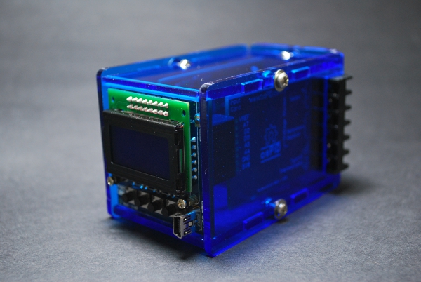
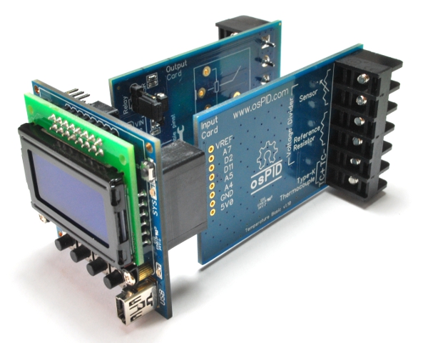
The
osPID consists of a main board which contains an Auduino-compatible
CPU as well as the LCD display, USB jack, and four input buttons on
its front side and two edge connectors for input and output cards on
its back side. The input card will receive temperature input from
either a thermistor or a type K thermocouple sensor. The output card
has two relay outputs and one digital output for connecting an
external solid state relay (SSR).
Pictures of the osPID with and without its covers are below.
Thermocouple. Actual temperature in the reflow oven is measured by the type K thermocouple. The sensor end of the thermocouple is placed adjacent to the circuit board in the oven cavity, and the leads at the other end are connected to the appropriate ports on the osPID. SparkFun, the supplier of the thermocouple that I used for this project, suggests that the thermocouple bead be clipped to the PC board to avoid overheating the components on the board due to a possible difference in air temperature and board temperature during the reflow cycle29
SSR.
The
solid state relay (SSR) is driven by the osPID. The relay used in
this project is specified to handle 40 amps. I
chose to use an SSR rather than a mechanical relay due to the
well-known advantages of the SSR, which include (but are not limited
to) faster switching time, acoustically silent operation, greater
lifetime, and clean bounceless operation30.
III. Construction. Construction of the reflow oven was extremely simple. It consisted of:
1. Removal of unnecessary parts from the toaster oven.
2. Rewiring the oven heating elements.
3. Threading the thermocouple into the oven cavity and connecting it to the osPID.
4. Installing the SSR in a cabinet and adding a connector to the box for the osPID connection.
First I disassembled the toaster oven and removed the two control boards, which would not be needed because the osPID would be controlling the power to the infrared heating elements. Pictured below are the oven parts (except for the shell) after disassembly on the left, and the “extra” circuit boards that were removed from the oven and not reinstalled on the right.
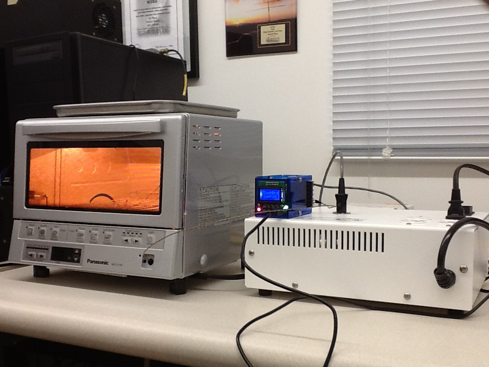
Below is a view of the reflow oven system in operation.
IV. Software.
The power, versatility, and extendability of the osPID are in its open
source software. The software consists of two parts, the firmware
installed in non-volatile memory on the osPID, and the user
interface, which runs under Microsoft Windows on a PC. The osPID can
be run in free-standing mode without a PC, but its operations are
greatly enhanced when it is used with a PC, as the temperature curve
inside the oven can then be viewed graphically in real time
As
noted above, the
firmware
is based on Brett Beauregard's Arduido PID Library. A basic
discussion of this software can be found on the Auduino Playground
website31.
The code itself is hosted on GitHub32.
Further description of the code by Brett Beauregard can be found on his
project blog33.
Reading this blog will really help you understand the workings of the
firmware. After reading the blog you could yourself write the code
for an excellent PID. If you read the blog, don't forget to click “Next” at the
bottom of each page to go to the next.
The
user interface software, or front-end software, was also written by
Brett Beauregard and can be downloaded either from the Auduino
Playground webpage referenced above (31), or directly from the zip
file link referenced here34
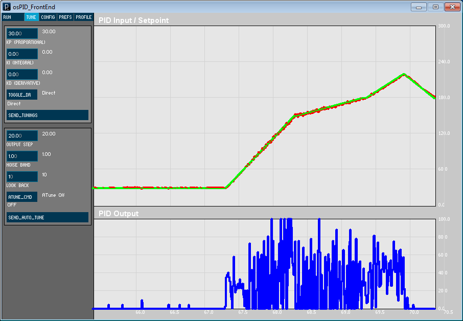
The image below shows the GUI. On the left side of the GUI are fields to
set Kp, Ki, and Kd as well as other parameters used to fine-tune the
controller. On the right (or above, depending on your browser) are, on top, the desired temperature curve
vs time in green and the actual achieved temperature curve vs time
in red. On the bottom is a display of the actual PID output vs time.
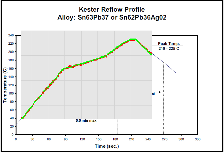
V. Results. The results achieved with this homebrew reflow oven have been quite acceptable. In the illustration on the left I have superimposed the programmed and actual temperature curves from a reflow run using this oven on the desired Kester Reflow Profile. The fit is quite good.
References for this web page are below.
Roger Rehr
W3SZ
April 7, 2015