
I have been having good success with my 630m station performance for both transmit and receive, although as previously mentioned I want to improve my transmit antenna and have plans to do so in short order.
I had originally planned to right-off-the-bat optimize the matching of my transmit antenna, but when I installed it I quickly saw that although the impedance was mismatched at the antenna end of the coaxial transmission line, the apparent SWR was not bad (less than 2:1) at the amplifier position in the shack, due to the effects of common mode current and the impedance transformation produced by the particular length of coaxial cable that runs from the antenna to the transmitter. So I lazily decided to not worry about getting better antenna tuning until I put up a more permanent transmit antenna. And then when I started having good success, any thought of messing with additional matching at this point vanished.
So I have been running with the antenna tuned to resonance at my transmit frequency of 0.47457 MHz but with an impedance mismatch, all of this being measured at the input to the low pass filter attached to the input to the variometer at the base of the inverted L. The image below shows the VNA results with the VNA attached at this point, at the base of the inverted L:

You can see that at the resonant frequency of 0.475 MHz at the base of the antenna SWR = 2.96, Z = 18.4 ohms, Rs = 17.2 ohms, Xs = -6.6 ohms, and phase = -163 degrees.
With the inverted L tuned in this manner, in the shack all looks well, with a nice low SWR, and with the Wattmeter on the ENI 1040L amplifier telling me that all of the power put out by the amplifier (120 Watts) is going to the load, with no reflected power being measured back at the amplifier.
Not being much of an RF guy, I figured that this tuning was the best I could do until I finished matching the antenna by correcting the impedance mismatch. So I wasn’t worried about pursuing things further before putting up the planned new transmit antenna, which should go up “any day now”.
But last week there was an interesting posting on the 600 Meter Group email list by Ike Blevins, KW7T which I’ve quoted here:
Signed on 630m cw back in January. Made a couple of contacts with my trusty homebrew 6AG7/1625 low powered transmitter. Of course I’ve read all the comments about measuring antenna current, but kept right on saying to myself…..too much fuss and trouble and probably won’t make any difference anyway. Yeah, right!
Long story short, thoughts about measuring the antenna current kept nagging at me until this morning I decided only one way to find out. Dug around in the junk box for about an hour, found the parts and after months of putting it off, made a junk box RF ammeter in about 20 minutes. Didn’t have to buy a single item.
Hooked the meter between the coax out and the loading coil tap at the base of my old ground mounted Hustler 6BTV, which I have modified for 630m (about 30 ft. tall). Key down and everything looked normal, but no reading at all on the RF current meter. Mmmmmmmm…..must have wired something wrong or found bad parts. But, on a hunch, before starting over again from scratch, I decided to move the input to a different tap on the loading coil. When I first made the loading coil I added several other taps, but ended up using the one that seemed to work the best (wrong!!). Moved the tap two turns from where it was and the RF meter came alive, from zero to PEGGED!
Spent two hours goofing around with different shunt values so as to get the meter in mid range. Otherwise, no way to know which way to go with the inductance for max RF transfer.
Right now I’m just in the ballpark, with more trimming to do, but thanks to the RF current meter I’m now getting at least TEN TIMES more power into the antenna! When you begin with 20 watts max, that’s a real big jump.
Now my plate dip, forward power out, max RF antenna current, and max field strength readings are all occurring at the same time in tuning. Moreover, I’m rockbound, and though I have several 473.5 khz crystals, none of them ever worked until now (old FT-241’s). So I was pretty much stuck on either 474.5 or 472.7 khz. So even though the transmitter uses a separate tube for the crystal oscillator, somehow my less than accurate loading of the final, due to antenna mismatch, was reflecting all the way back to the 6AG7 and preventing it from working with some crystals.
Whole new world down below the broadcast band. The old fly by the seat of your pants, clip and trim, close is good enough, etc…..a sure recipe for failure. Another lesson learned the hard way. Spend an extra 1% of your time doing it right and save yourself months of 99% frustration and mediocre results. Looking back, nothing short of a miracle that I made any cw contacts at all 🙂
Because LFers in the know seem to really hang their hats on putting an RF ammeter at the input to the antenna as the best way to maximize the power you are really sending into the ether, I had already procured several RF ammeters prior to reading Ike’s email. I had obtained the RF ammeters on eBay at bargain-basement prices, as they were being sold as “Steampunk” decorations rather than as RF devices. They looked like they were in great shape from their pictures, so I took a chance and purchased them. For those of you who aren’t familiar with Steampunk, it is a style of design and fashion that combines historical elements with anachronistic technological features inspired by science fiction. Here is a brief article describing it.
After reading Ike’s note, I decided that it was time for me stop being lazy, and to put one of my Steampunk devices to work. So I put the RF ammeter between the antenna terminal on the variometer and the bottom end of the inverted L, as is shown below:

There is less than a foot of 50 ohm coaxial cable between the variometer and the low pass filter, and then there is about 150 feet of coax between the low pass filter and the amplifier.
When I hooked up the ammeter as shown above with the variometer tuned to resonance at the operating frequency and then retuned the variometer for maximum antenna current, I got a huge increase in antenna current. Then I took a quick look to see what was going on in the shack. The image of the wattmeter on the amplifier’s front panel that I saw in my cellphone showed that instead of reading 120 watts as it had been before, it was reading more than 300 watts forward output. So I quickly turned down the drive to the amplifier so that I would get a similar reading on the wattmeter on the amplifier to what I was getting before, roughly 120 watts. According to the meter on the amplifier, only 60 of these 120 watts were reaching the load, with the remainder being reflected. Reducing the indicated power from 300+ watts to 120 watts resulted in my reducing the drive level in my PowerSDR software from 30 to 2! So if I was operating in the linear portion of the amplifier’s curve, I had reduced my power output from the amplifier from about 120 watts down to 8 watts. Interestingly, with the drive level at only 2 and with the amplifier putting out 8 watts with the new variometer tuning, I was still getting 2 amps of antenna current, which is what I got with 120 watts of transmitter power output with the old variometer tuning (antenna tuned to resonance at the operating frequency).
So why was the wattmeter on the amplifier indicating more than 300 watts out? Because the wattmeter depends on seeing a 50 ohm load for accurate results. When the impedance is significantly removed from 50 ohms the wattmeter will not give accurate results. To get a better idea of what power I was actually putting out with a PowerSDR drive level of 2, I ran the amplifier into a 50 ohm dummy load using this amount of drive, and the wattmeter showed a bit less than 10 watts, about 8 watts, just as the calculation predicted.
With the variometer now tuned to give maximal antenna current, the VNA results with the VNA hooked up to the LPF at the base of the inverted L now looked like this:

You can see that the resonant frequency is now 0.464 MHz, about 11 kHz below the operating frequency of 0.4757 MHz. At the resonant frequency, Z is 20.3 ohms, Rs is 17.6 ohms, Xs is -10.1 ohm, and phase is -154 degrees. But look at the results at the operating frequency of 0.475 MHz! The impedance is 50.9 ohms, very close to the 50 ohm impedance of the coaxial transmission line. So although the SWR is now lousy in the shack, with the “antenna” impedance matched to the transmission line there is maximal transfer of power from the transmission line to the antenna. Holy complex conjugate! For fun, I detuned the variometer and then adjusted it using the VNA to achieve as close to 50 ohms as I could for the impedance measured by the VNA at the input to the low pass filter at the base of the antenna at my operating frequency of 0.4757 MHz. I then disconnected the VNA and checked the antenna current using the RF ammeter (which I now leave in the circuit at all times, as removing it changes the match slightly). Adjusting the VNA to give a 50 ohm impedance at the operating frequency always resulted in peak antenna current. Nice!
So what does the match look like at the amplifier in the shack with the new settings that maximize power transfer to the antenna? It is not pretty!:
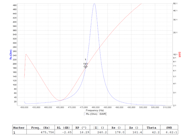
You can see that the SWR has jumped from less than 2 to greater than 6 and that the impedance is 240 ohms, with a substantial reactive component (Xs = 161.4). But nevertheless, FAR MORE power is now being delivered to the antenna.
Since changing the tuning I have been running WSPR with just 8 watts and I am getting WSPR reports that are similar than what I was getting running 120 watts before changing the tuning as outlined above. This result makes sense, since the antenna current under the two conditions is the same. The amplifier that I am using is specified to be protected from damage when it is running at 400 watts output into anything from a short circuit to an open circuit at all phase angles. So I do not think that running 8 watts even at an SWR of more than 6 is likely to damage it. It has an “overload” circuit that trips if it receives excessive reflected power, and that circuit has not been activated.
What would it take to match the load properly? Well, it would actually be very simple to achieve a good match, and if I were not planning to retire this antenna in a few days I would order the necessary parts and do it.
I put the values obtained by the VNA placed at the input to the LPF at the base of the antenna at the operating frequency of 0.4757 MHz with the variometer adjusted to give resonance at that frequency (Rs = 17.2, Xs = -6.6, phase = -163 degrees) into ON4UN’s L Network Calculator, and it showed that an L network with a series inductance of 10.18 uH and a shunt capacitance of 9262 pf will match the impedance presented when the variometer is so tuned:
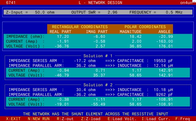
The desired result is solution #2 in the image. There are always at least 2 solutions, and sometimes 4. You DO NOT want the first solution because a series capacitor or a parallel inductor would result in very high RF voltages. And a series capacitor would need to tolerate the entire RF current going to the antenna. These problems are not present with the second solution.
To check the solution, I put the calculated values into Wes Hayward’s Smith Chart program, and you can see that the calculated values produce an excellent result, with an SDR of 1.0078. The blue dot at the origin (r=1 on the horizontal axis) indicates a “perfect” SWR obtained by this matching network. The white cross slightly below the horizontal axis between r=0 and r=0.5 is the “starting point” before matching with the L network:

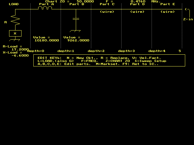
The schematic used to create the Smith Chart is here:
The ON4UN software was included in my copy of the 4th edition of his book, ON4UN’s Low-Band DXing. Unfortunately, the software won’t run with modern Windows versions. So I run it on my 64 bit Windows 10 machine by using vDos, a DOS emulator. vDOS is recommended by PCWorld, and it is free, so it wasn’t hard for me to decide to use it.
The Smith Chart software by Wes W8ZOI was included in his book Introduction to RF Design. It must also be run on an old Windows machine or using vDOS on a modern Windows machine.
You can read more about RF Ammeters for LF use here.
I hope that you found the above interesting!
73,
Roger Rehr
W3SZ